The C7222 Pico W board is a very simple I/O board intended as a getting-started platform for Raspberry Pi Pico W development. It provides a UART connector, a reset button, four user buttons, and three red/green LED pairs so core embedded workflows can be tested quickly with minimal hardware complexity.
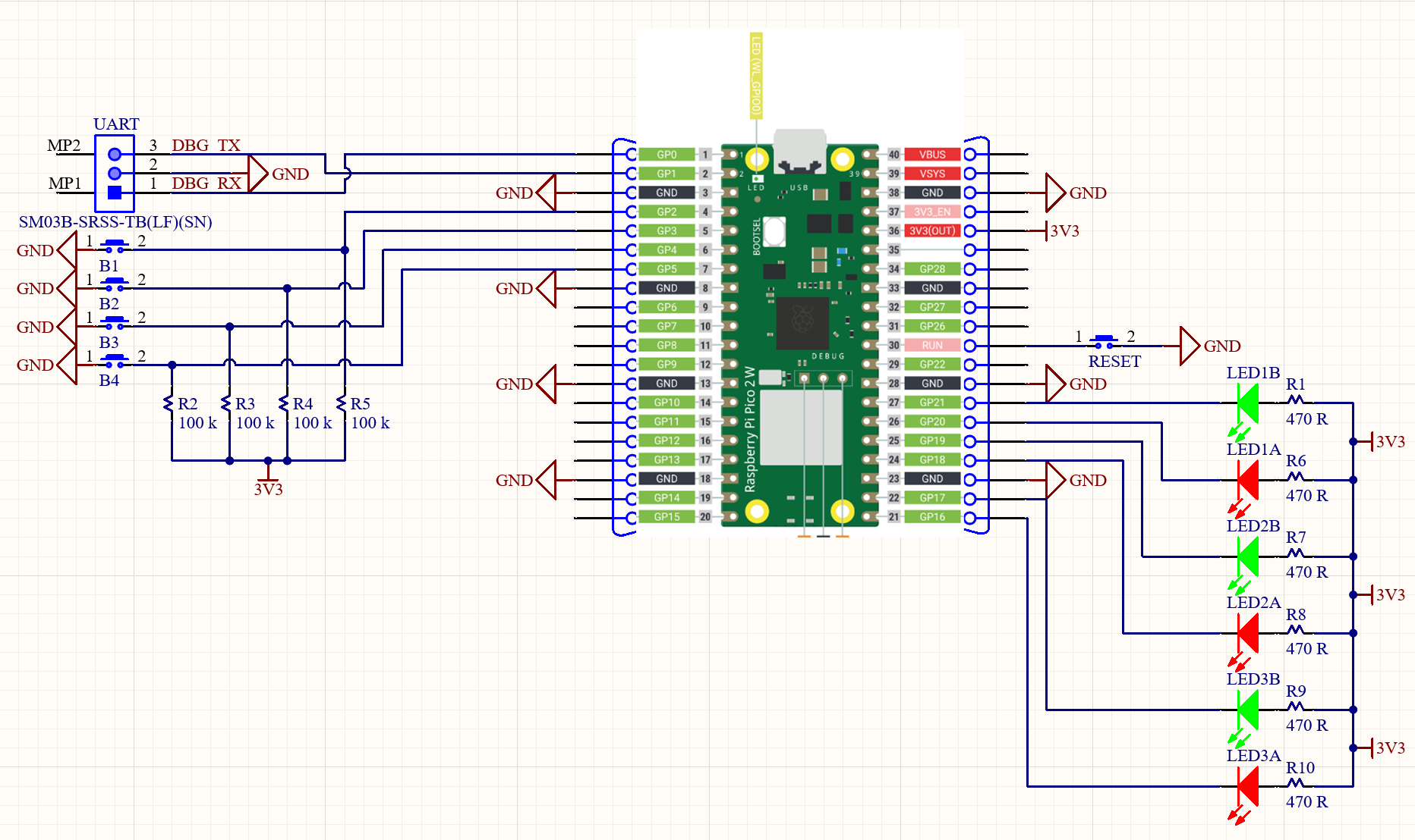
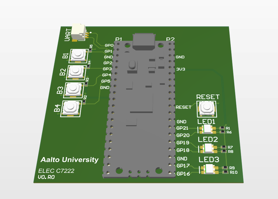
The schematic is shown in the image above. The 3D board view below is for reference only.
This document summarizes the external interfaces and GPIO assignments for the C7222 Pico W board, based on the schematic.
Board Overview
The board is built around a Raspberry Pi Pico W. It exposes:
- A debug UART header.
- Four push buttons with pull-ups.
- Three dual‑color LED pairs (red/green).
- A reset switch tied to RUN.
GPIO Assignments
LEDs (active‑low)
Each LED is tied to 3V3 through a 470 Ω resistor. The GPIO drives the LED low to turn it on (active‑low).
LED1_RED→GP21LED1_GREEN→GP20LED2_RED→GP19LED2_GREEN→GP18LED3_RED→GP17LED3_GREEN→GP16
These match the C++ API enums:
PicoWBoard::LedId::LED1_RED = 21PicoWBoard::LedId::LED1_GREEN = 20PicoWBoard::LedId::LED2_RED = 19PicoWBoard::LedId::LED2_GREEN = 18PicoWBoard::LedId::LED3_RED = 17PicoWBoard::LedId::LED3_GREEN = 16
Buttons (active‑low)
Each button pulls the GPIO to GND when pressed, with a 100 kΩ pull‑up to 3V3.
BUTTON_B1→GP2BUTTON_B2→GP3BUTTON_B3→GP4BUTTON_B4→GP5
These match the C++ API enums:
PicoWBoard::ButtonId::BUTTON_B1 = 2PicoWBoard::ButtonId::BUTTON_B2 = 3PicoWBoard::ButtonId::BUTTON_B3 = 4PicoWBoard::ButtonId::BUTTON_B4 = 5
Debug UART Header
The UART header exposes the Pico’s UART signals:
DBG_TX→GP0DBG_RX→GP1GND
Notes:
- This is the default UART for Pico platforms and is enabled out of the box for
stdio/printfoutput. - When using a Pico Debugger, the UART wires must be crossed: board
DBG_TXgoes to debuggerRX, and boardDBG_RXgoes to debuggerTX. - If using the Pico Debugger provided cables, the female and male pin cables can be attached as follows:
- Female black ↔ male black
- Female orange ↔ male yellow
- Female yellow ↔ male orange
Reset
The RESET switch ties the Pico RUN pin to GND to reset the board.
Usage Notes
- LEDs are active‑low: write
0to turn on,1to turn off. - Buttons are active‑low: pressed = logic
0, released = logic1. - The GPIO assignments are fixed by hardware; use the enums in
c7222_pico_w_board.hppfor clarity. - LED drive relies on the Pico’s sink capability (drive strength). This is not optimized for low‑power operation.